NICEIC Domestic Installer
Guides
Earth fault loop impedance explained
Why electricians measure Zs and Ze, and what the limits in BS 7671 mean for your installation.
Published · Updated · By 2K Electrical Services
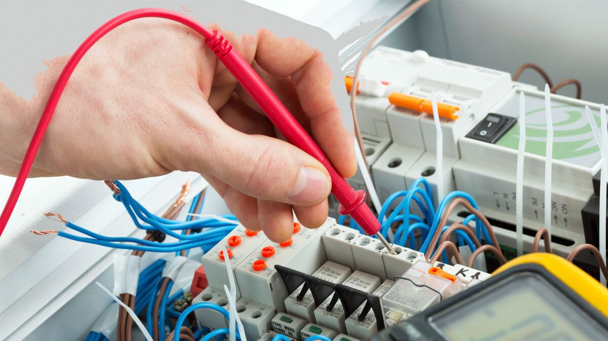
If you have watched an electrician test a circuit, you will have seen them plug a tester into a socket and read a number in ohms. That number is usually the earth fault loop impedance, and it decides whether the circuit’s protective device will switch off quickly enough to save a life when something goes wrong.
What the loop is
When a live conductor touches earth, for example inside a damaged appliance with a metal case, fault current flows round a loop: from the transformer, along the live conductor, through the fault, back along the earth conductor and the supply’s earth path to the transformer. The total opposition to current round that loop is the earth fault loop impedance, written Zs.
Supply voltage divided by Zs gives the fault current. The lower the impedance, the higher the fault current, and the faster the fuse or circuit breaker operates. Too high an impedance means a fault could sit there heating cables and making metalwork live without ever tripping anything.
Ze and Zs
- Ze is the external part of the loop, measured at the incoming supply with the installation disconnected. Typical maximum values declared by distributors are 0.8 Ω for a TN-S supply (separate earth), 0.35 Ω for TN-C-S (PME, the most common in London, and the PNB arrangement recognised by Amendment 4 of BS 7671) and 21 Ω plus the electrode resistance for a TT supply (earth rod).
- Zs is the whole loop measured at the far end of each circuit. It equals Ze plus the resistance of the circuit’s live and earth conductors.
The limits
BS 7671 requires every final circuit to disconnect within a set time under fault conditions: 0.4 seconds for most circuits up to 63 A in a TN system, 5 seconds for distribution circuits (Regulation 411.3.2). Tables 41.2 to 41.4 give the maximum Zs for each type and rating of fuse or circuit breaker. Because the tables already include a factor for the supply voltage being at the low end of its tolerance, the electrician checks that the measured Zs is no more than the tabulated value, after correcting for conductor temperature, which in practice is often done with the rule of thumb that the measured value should be no more than 80 % of the table figure.
Where an RCD provides the fault protection, the limits are far more relaxed because the RCD trips on a few milliamps rather than hundreds of amps. Table 41.5 gives those values, and on a TT supply the installation must also meet RA × IΔn ≤ 50 V, which keeps exposed metalwork below a safe touch voltage.
Why the test can trip your RCD
A loop tester briefly draws current to earth to make its measurement. On a circuit protected by an RCD that can be enough to trip it, which is a nuisance in an office or dangerous where equipment must not lose power. Modern testers use a low-current method, typically 15 mA, to measure without tripping, and electricians plan tests on live installations accordingly.
What it means for you
If your EICR mentions a high Zs, the usual causes are a poor connection somewhere in the earth path, an undersized cable, or a supply earth that is no longer adequate. It is a C2 or FI observation depending on the circumstances, and it needs investigating rather than ignoring.